Francisco Javier Cruces Doval
Friday, September 8, 2023 | 10 minutes
IPv6 Tunnels
Introduction
In this detailed post, we explore the process of configuring IPv6 to IPv4 tunnels and vice versa in Linux and Cisco environments. As the migration to IPv6 gains importance, the ability to establish communication between IPv4 and IPv6 networks becomes essential. We will cover the basics of tunnel configuration, including the most common types of tunnels, such as 6to4 and Teredo. Additionally, we will provide step-by-step instructions for configuration on both Linux systems and Cisco devices.
6to4 Tunnels in Cisco
1. Configuration of Router Network Interfaces
R1
- FastEthernet 0/0
- Network Prefix:
3333:db7::/64 - Link:
FE80::C801:20FF:FE69:0 - Global:
3333:DB7::C801:20FF:FE69:0
- Network Prefix:

- FastEthernet 1/0

- FastEthernet 2/0

For R1 router clients, we will configure SLAAC:

R2
- FastEthernet 0/0
- Network Prefix:
3333:db7:1::/64 - Link:
FE80::C802:20FF:FE79:0 - Global:
3333:DB7:1:0:C802:20FF:FE79:0
- Network Prefix:

- FastEthernet 1/0

- FastEthernet 2/0

For R2 router clients, we will configure SLAAC:

R3
- FastEthernet 0/0
- Network Prefix:
3333:db7:2::/64 - Link:
FE80::C803:20FF:FE89:0 - Global:
3333:DB7:2:0:C803:20FF:FE89:0
- Network Prefix:

- FastEthernet 1/0

- FastEthernet 2/0

For R3 router clients, we will configure SLAAC:

Note: In this scenario, it is not necessary to manually configure IPv4 routes, as the network interface configuration will make IPv4 traffic routable.
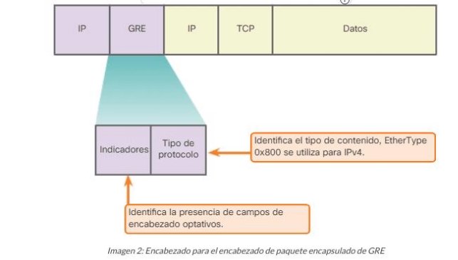
2. GRE Tunnels
GRE is an unsecured site-to-site VPN tunneling protocol that can encapsulate a wide variety of protocol packets within IP tunnels. This allows an organization to transmit other protocols over an IP-based WAN.

This allows adding an IPv4 header to an IPv6 packet so it can travel over IPv4 networks.
R1 → R3
We will create a tunnel interface:

GRE Tunnel Configuration with IPv6 over IPv4
We set the tunnel mode to GRE with IP, which will encapsulate our IPv6 packets within IPv4:

We assign an IPv4 address to our tunnel:

We set the WAN address of our router, FastEthernet 1/0:

We set the WAN address of the tunnel endpoint (R2):

We enable OSPF, which is a dynamic routing protocol:

This command adds the tunnel network to OSPF:

We assign an IPv6 address to our tunnel, with the network prefix 2002 based on the router’s IPv4 address 2002:0A00:0001::1/64:

We create the route to reach the network:

We create a tunnel interface:

We set the tunnel mode to GRE with IP, which will encapsulate our IPv6 packets within IPv4:

We assign an IPv4 address to our tunnel:

We set the WAN address of our router, FastEthernet 1/0:

We set the WAN address of the tunnel endpoint (R2):

We enable OSPF, which is a dynamic routing protocol:

This command adds the tunnel network to OSPF:

We assign an IPv6 address to our tunnel, with the network prefix 2002 based on the router’s IPv4 address 2002:0A00:0002::1/64:

We create the route to reach the network:
We create a tunnel interface:

We set the tunnel mode to GRE with IP, which will encapsulate our IPv6 packets within IPv4:

We assign an IPv4 address to our tunnel:

We set the WAN address of our router, FastEthernet 1/0:

We set the WAN address of the tunnel endpoint (R2):

We enable OSPF, which is a dynamic routing protocol:

This command adds the tunnel network to OSPF:

We assign an IPv6 address to our tunnel, with the network prefix 2002 based on the router’s IPv4 address 2002:1400:0001:

We create the route to reach the network:
R3 → R1
We create a tunnel interface:

We set the tunnel mode to GRE with IP, which will encapsulate our IPv6 packets within IPv4:

We assign an IPv4 address to our tunnel:

We set the WAN address of our router, FastEthernet 1/0:

We set the WAN address of the tunnel endpoint (R2):

We enable OSPF, which is a dynamic routing protocol:

This command adds the tunnel network to OSPF:

We assign an IPv6 address to our tunnel, with the network prefix 2002 based on the router’s IPv4 address 2002:1400:0002::1/64:

We create the route to reach the network:

R3 → R2
We create a tunnel interface:

We set the tunnel mode to GRE with IP, which will encapsulate our IPv6 packets within IPv4:

We assign an IPv4 address to our tunnel:

We set the WAN address of our router, FastEthernet 1/0:

We set the WAN address of the tunnel endpoint (R2):

We enable OSPF, which is a dynamic routing protocol:

This command adds the tunnel network to OSPF:

We assign an IPv6 address to our tunnel, with the network prefix 2002 based on the router’s IPv4 address 30.0.0.2 → 2002:1e00:0002::1/64:

We create the route to reach the network:

R2 → R3
We create a tunnel interface:

We set the tunnel mode to GRE with IP, which will encapsulate our IPv6 packets within IPv4:

We assign an IPv4 address to our tunnel:

We set the WAN address of our router, FastEthernet 1/0:

We set the WAN address of the tunnel endpoint (R2):

We enable OSPF, which is a dynamic routing protocol:

This command adds the tunnel network to OSPF:

We assign an IPv6 address to our tunnel, with the network prefix 2002 based on the router’s IPv4 address 30.0.0.1 → 2002:1e00:0001::1/64:

We create the route to reach the network:

3. Functionality Verification
We will verify that the tunnels have been created. To do this, we will enter the following command on the three routers in our scenario:


This will appear once both ends of the tunnel have been created. If not, nothing will appear. In our case, we can see that the tunnels have been successfully created.
Ping
We will verify the functionality of the tunnels by performing a ping.
- PC1 → 3333:db7::e60:ddff:fea6:0
- PC2 → 3333:db7:1:0:e2e:3bff:fe83:0
- PC3 → 3333:db7:2:0:e62:5dff:fedf:0
PC1 → PC2

PC1 → PC3

PC2 → PC1

PC2 → PC3

PC3 → PC1

PC3 → PC2

We can see that we have connectivity between all the machines in our scenario using IPv6, even though we have to traverse IPv4 networks.
Traceroute
We will verify the path that the packets follow.
Path of a packet from PC1 to PC2:

Path of a packet from PC1 to PC3:

Path of a packet from PC2 to PC1:

Path of a packet from PC2 to PC3:

Path of a packet from PC3 to PC1:

Path of a packet from PC3 to PC2:

4. Study of an Encapsulated Packet
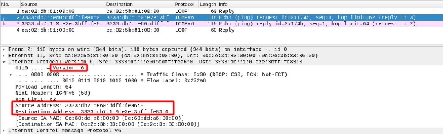
Before Passing Through the Tunnel
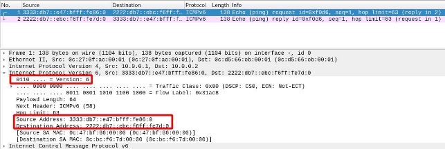
A packet traveling from PC1 to PC2.
We can see that, since it has not yet passed through the tunnel, it does not have IPv4 headers, only IPv6. We can see that the source is PC1 and the destination is PC3:
We will see how, in the next segment, once it passes through the tunnel, the router will add an IPv4 header so it can traverse that segment.
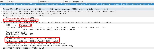
After Passing Through the Tunnel
If we look at a packet that has passed through a tunnel, we can see that it has “2 network layers”:

If we look at the network layer, we see that the source and destination IPs are those of the tunnel endpoints. Additionally, we see that it uses protocol 47, which means it has passed through a GRE tunnel.

Finally, we can see in the IPv6 header that it is indistinguishable from one that has not passed through a tunnel.
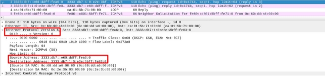
Once It Reaches the Destination Network
We see that, once it reaches the destination (i.e., after traversing the IPv4 segment and re-entering the IPv6 network), the router will remove the IPv4 header and leave the IPv6 header so the packet can reach its destination.
We see that the IPv6 header remains intact; it is the same throughout the packet’s journey:
6to4 Tunnels in Linux
1. Network Interface Configuration
I will respect the IPv4 addresses from the Cisco scenario.
R1
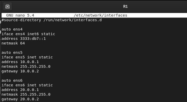
To apply the configuration, we will run sudo systemctl restart networking.service.
I will configure SLAAC to set up the clients on our IPv6 network. First, we need to install the radvd package with sudo apt install radvd.

Once the service is configured, we will restart radvd, and our clients will automatically configure themselves with the specified prefix.
R2

To apply the configuration, we will run sudo systemctl restart networking.service.
I will configure SLAAC to set up the clients on our IPv6 network. First, we need to install the radvd package with sudo apt install radvd.

Once the service is configured, we will restart radvd, and our clients will automatically configure themselves with the specified prefix.
R3
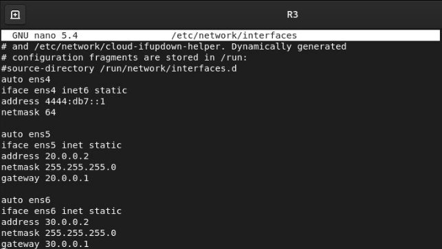
To apply the configuration, we will run sudo systemctl restart networking.service.
I will configure SLAAC to set up the clients on our IPv6 network. First, we need to install the radvd package with sudo apt install radvd.

Once the service is configured, we will restart radvd, and our clients will automatically configure themselves with the specified prefix.
Note: In this scenario, it is not necessary to manually configure IPv4 routes, as the network interface configuration will make IPv4 traffic routable.
However, it will be necessary to enable the forwarding bit for both IPv4 and IPv6 on all routers.
To do this, we edit the file sudo nano /etc/sysctl.conf and uncomment the following lines:
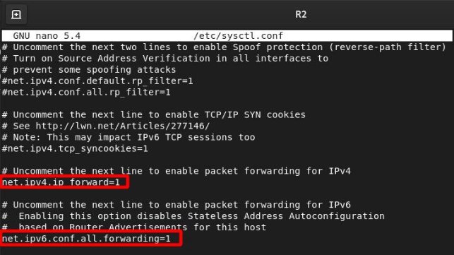
We will repeat this for each of our routers and reboot to apply the changes.
2. SIT Tunnel Configuration
The operation is similar to GRE tunnels in Cisco. This will take our packets and, through a tunnel interface, add an IPv4 header so they can traverse IPv4 networks.

Once the tunnel is up, we will tell the router that to reach the prefix of network X, it must use this tunnel to add the header to our packets.

For convenience, I have created a small script on each router with the necessary commands to make the tunnel work.
It consists of 4 commands:
- It will create the tunnel interface with the destination and then the source.
- It will bring up the network interface.
- It will assign the IPv6 address to the tunnel based on the source IPv4 address.
- We will create the route for the traffic that will use the tunnel.
We can name the tunnel as we wish. In my case, I have named it tunnel followed by a number to identify them.
R2 Tunnels
This is what the “script” for R2 tunnels would look like:

Once the script is created, we will give it permissions and execute it:

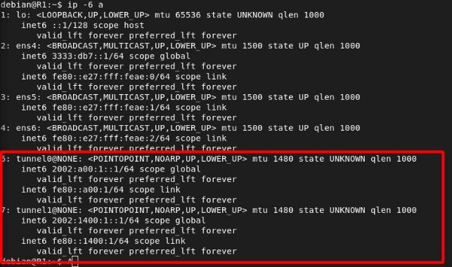
We will verify that the interfaces have been created correctly:

R3 Tunnels
This is what the “script” for R3 tunnels would look like:

Once the script is created, we will give it permissions and execute it:

We will verify that the interfaces have been created correctly:

3. Functionality Verification
- PC1 → 3333:db7::e47:bfff:fe86:0
- PC2 → 2222:db7::ebc:f6ff:fe7d:0
- PC3 → 4444:db7::e43:78ff:fec6:0
Ping
PC1 → PC2

PC1 → PC3

PC2 → PC1

PC2 → PC3

PC3 → PC1

PC3 → PC2

Traceroute
Once we have verified connectivity, we will check if the packets use the tunnels.
PC1 → PC2

PC1 → PC3

PC2 → PC1

PC2 → PC3

PC3 → PC1

PC3 → PC2

4. Study of an Encapsulated Packet
Before Passing Through the Tunnel
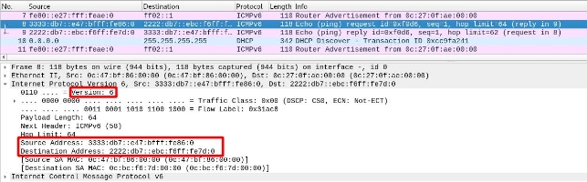
A packet traveling from PC1 to PC2.
We can see that, since it has not yet passed through the tunnel, it does not have IPv4 headers, only IPv6. We can see that the source is PC1 and the destination is PC3:
We will see how, in the next segment, once it passes through the tunnel, the router will add an IPv4 header so it can traverse that segment.
After Passing Through the Tunnel
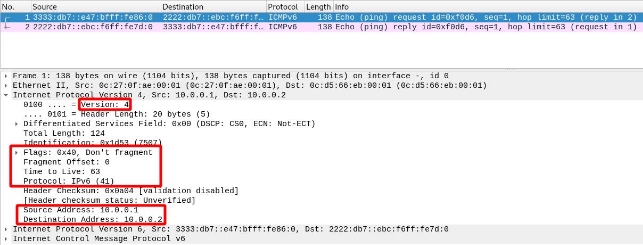
If we look at a packet that has passed through a tunnel, we can see that it has “2 network layers”.
If we look at the network layer, we see that the source and destination IPs are those of the tunnel endpoints. Additionally, we see that it uses protocol 47, which means it has passed through a GRE tunnel.
Finally, we can see in the IPv6 header that it is indistinguishable from one that has not passed through a tunnel.
Once It Reaches the Destination Network
We see that, once it reaches the destination (i.e., after traversing the IPv4 segment and re-entering the IPv6 network), the router will remove the IPv4 header and leave the IPv6 header so the packet can reach its destination.
We see that the IPv6 header remains intact; it is the same throughout the packet’s journey: